Getting Started using FSC(SM) Integration
Control Architect supports the importing of FSC(SM) exported project configuration data for integration of PLC Modbus data through PKS PCDI Channel blocks and PKS SCADA point blocks. The import process imports exported Safety Builder documents and generates Control Modules that contain a single embedded block to represent a PLC Controller and blocks to represent PLC Logic Programs. Users can now see the Modbus address and PLC Alias name being referenced in their Control Strategies when viewed in a Chart View. A Program Logic viewer allows users to view the Logic as a PDF view. A Variable list allows users to navigate to its usage in the Program Logic.
FSC Controllers that purely integrate into a C300 CDA using gateways are imported such that a FLD Peer Control Module will be created for each FLD that is integrated into the C300.
Prepare PKS Configuration Snapshot
A new PKS configuration Collection snapshot must be created using a minimum Control Architect release of 21.11.3. Beginning with this release during the import of PKS Server configuration special processing is added for PCDI Channel Block connections to support PLC Modbus connectivity. Existing configuration snapshots created with an earlier release are not supported for PLC Modbus connectivity.
If your configuration project consists entirely of SCADA, then having to rebuild existing configuration snapshots is not required as there are no additional connection processing required for SCADA points.
Exporting data from Safety Builder application
Building the Project Export Folder Content
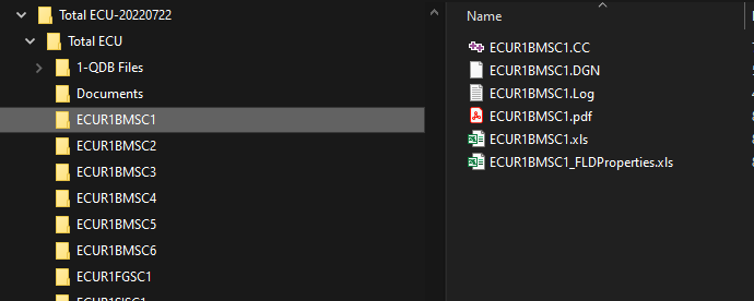
The data required for importing into a configuration project Collection snapshot must reside in a folder hierarchy similar to below. The root folder path "Total ECU" is then referenced in the Import tool when choosing to import FSC type PLC configuration.
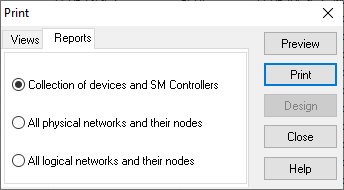
Collection of devices and SM Controllers Document
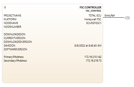
To begin importing Safety Builder exported data sources, the "Collection of devices and SM Controllers" report must be printed to a PDF document type. This document will be read to extract its Project Information and Modbus Communications IP Address data. These properties are used to generate a unique PLC Controller Strategy name and these property values are cached in this new PLC Controller Strategy to support future version comparison operations. Modbus Communications IP Address data is also parsed to allow resolving of PKS Scada Controller and its point Modbus addresses.
| | This referenced document is not required when choosing to import Safety Builder configuration that is purely CDA integrated using gateways.
|
The "Network Configurator" view in the Safety Builder must be selected to print this document.
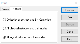
All logical networks and their nodes Document
The "All logical networks and their nodes" configuration document needs to be printed as a PDF document type. You can choose to name this anything as you will be required to browse for this particular PDF document file. This document provides the PCDI Communication bindings and the PCDI Device address.
| | This referenced document is not required when choosing to import Safety Builder configuration that is purely CDA integrated using gateways.
|
The "Network Configurator" view in the Safety Builder must be selected to print this document.
Application FLD Logic PDF Documents
All Program FLD Logic documents must be exported from Safety Builder as PDF document types using the File-Print menu item. This will display a "Print" window that allows you to choose the "All" option. While printing to a PDF the user will be prompted to provide a SaveAs PDF filename, which must be the exact name of the FSC Controller that contains this FLD logic. During import these Program FLD Logic documents will be imported to the MongoDB configuration snapshot where these FLD logic drawings can be viewed using the PLC Logic viewer. Program Logic strategies are also created during import that allow the user to launch a Program Logic viewer window for viewing logic and for navigating its used variable list.
The "Application Editor" view in the Safety Builder must be selected to print this document.
Excel (*.XLS) Data Files
The following Excel documents must be exported from Safety Builder as Excel *.XLS types.
| | The Safety Builder instance must have its privilege level elevated to export the "FLD Properties" document when the "Application Editor" view is selected. This is changeable by left mouse double-clicking in the bottom right pane of the Safety Builder application window.
|
Export these documents from Safety Builder by:
-
Select the "Point Configurator" view button
-
Click the "
Export Points" button from the main ToolBar or from the
File-Export Points... menu item
-
Use the default name provided, which will become the name of the FSC Controller and the xls file extension. The save location should default to the subfolder that is named from the active FSC Controller.
-
Select the "Application Editor" view button
-
Select the menu item
File-Import and Export- Export FLD Properties... menu item.
| | You must have elevated permission to export this document.
|
-
Use the default name provided, which will become the name of the FSC Controller with "_FLDProperties" appended to the filename along with the xls file extension. The save location should default to the subfolder that is named from the active FSC Controller.
Importing Safety Builder exported data into a Control Architect configuration project
Specify the Collection of devices and SM Controllers Document
The "Collection of devices and SM Controllers" PDF document must be available for browsing. You can choose to name this file using any valid filename.
This document is used to provide project information and Modbus IP Address data during import. The project information is used to provide description and last saved property data when generating the PLC Controller Control Module.
Specify the All logical networks and their nodes Document
The "All logical networks and their nodes" PDF document must be available for browsing. You can choose to name this file using any valid filename.
This document is used to provide Modbus PCDI bindings and Device Address data during import.
Program FLD Logic PDF Documents
Application FLD logic PDF documents are imported into your configuration snapshot where they can be viewed using the PLC Viewer.
Modbus Declaration Map
During import a mapping of all variables defined in the FSC Controller is created that also specifies where the Variables are used along with their Modbus Alias name, Modbus Address, and its PCDI Modbus address if used as a PCDI reference. This mapped document is used to resolve PCDI Channel and SCADA point block Modbus address references during the import operation. This map is also saved to the generated PLC Controller CM Strategy as a JSON type data collection.
Possible Errors when Resolving Modbus Connectivity
It is expected that no errors will occur during import, but reality is that at times what is configured in the DCS won't necessarily match what the PLC project has defined. For example a SCADA point strategy could be referencing a Modbus Address that is no longer defined in the PLC project
where the SCADA point should have been either deleted or updated to a new address. Failure to resolve these Modbus connections will be noted as an error in the Error tab view. Errors listed in this view are often indicative of a defect in the configuration.
Modbus references that could not be resolved will be displayed as an invalid Modbus reference.
Import results
Upon successful completion of an Import operation documents will have been imported into a MongoDB Database Collection that is logically named "PLCAssets". The documents that were imported consist of the Program Logic PDF files, Modbus Alias mapping, and Excel files.
Control Module Strategies that are created during Import
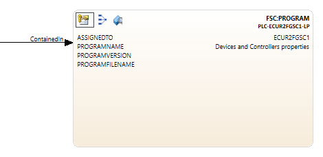
During import a number of strategies that represent both the PLC Controller node and its contained PLC logic programs are generated as Control Modules to fit within the PKS Control Strategy schema. Program Logic CM's are contained within the PLC Controller CM. Users can view the assigned and containment relationships by choosing to
group the configuration
Data View.
A single Control Module is generated to represent the PLC Controller node itself.
Control Modules that represent FSC PLC Program Logic are named using the format: NodeName where NodeName is the name of the FSC Controller node.
Overwriting Existing FSC Import
Users can choose to overwrite an existing import. If the imported PLC Controller Strategy name is the same as an existing, then it along with all its documents and generated Control Module strategies will be replaced or overwritten. Connections that were generated to support SCADA and PCDI relationships for the PLC Controller being imported are deleted prior to reimporting.
ChartView Visualization
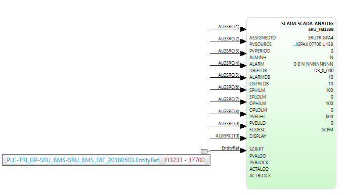
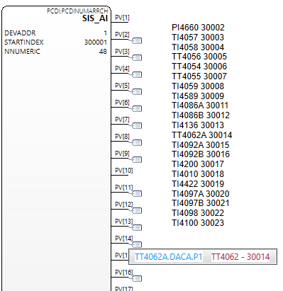
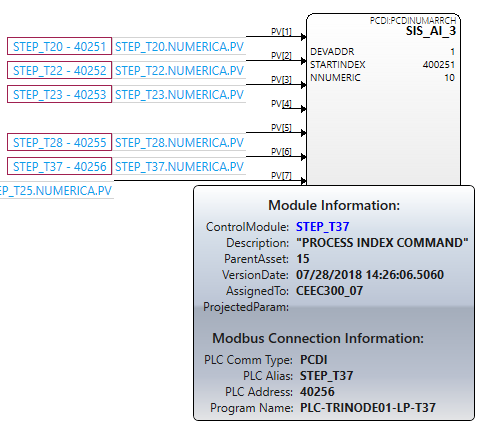
The Chart View has been enhanced to support the visualization of a Modbus connection type. These connection types are expected for PCDI Channel and SCADA point blocks.
Visualization of Modbus Connection types
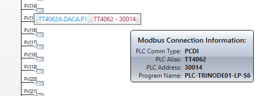
Here is an example of what to expect when viewing PCDI Channel blocks or SCADA point blocks within a Chart View.
When hovering your mouse over a Modbus connection type, additional information is displayed.
Viewing Program Logic
The Program Logic associated with a PLC Program Logic block can be viewed by clicking a button that becomes visible in the adorner layer of a Chart View block when the mouse enters a block visual.
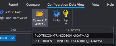
Program Logic can also be viewed from the Data View tab. The Ribbon Toolbar for the Data View tab contains a drop-down button that lists all PLC Assets that are discoverable in the current project configuration snapshot. This viewer allows you to view all logic programs and their variable usage within a single viewer unlike the Program Logic block that is scoped to only that PLC program itself.
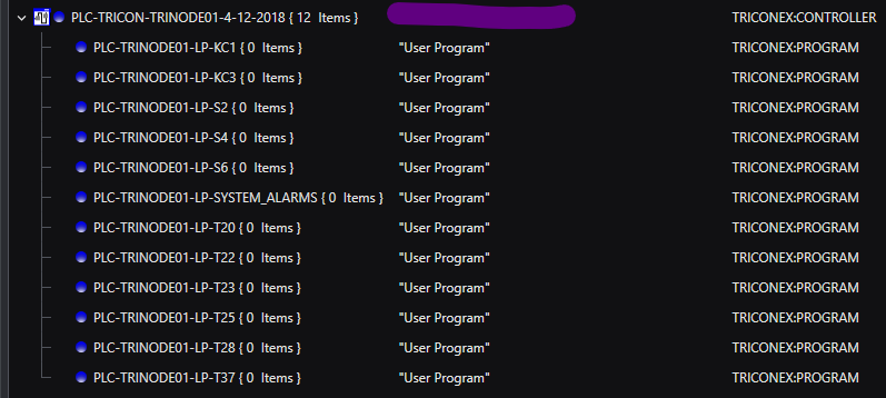
Use the grouping functions to see the containment relationship between a PLC (FSC) Controller block and its Program Logic blocks.
This view is grouped on the "AssignedTo" property.
Users can typically view their PCDI data by using the filter in the Data View to filter on Name or FunctionBlocks with the filter text "PCDI".
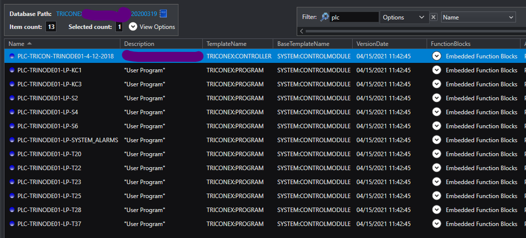
Users can also filter on the text "PLC" to achieve a similar related view of strategies associated with a Safety Manager project import.
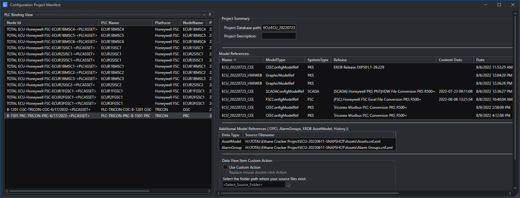
Viewing the Manifest Data
The Manifest Data that is created and maintained for each configuration snapshot provides history and information as to the contents of a configuration snapshot. This view is accessible from the configuration
Data View. This Manifest View provides the functions that allow you to attach or create a new binding between an existing PLC project import and the current configuration snapshot.
PLC Binding to a Configuration Project Database:Collection Snapshot
| | A future release will support the ability to bind an already imported Modbus asset to multiple Database:Collection configuration snapshots.
When a new configuration snapshot is created the user can choose to manually bind an existing PLC project entity to this new configuration snapshot rather than having to re-import the same PLC project information. This assumes that the PLC project configuration itself has not changed.
|
The existing Manifest View has been enhanced to support a new "PLC Binding View" Tool window. This view provides any future maintenance functions that will become available for working with imported Modbus assets.
